Selecting the right High Pressure Clamp requires more than matching a product photograph to a pipe. The clamp must suit the system’s working pressure, temperature, fluid, pipe diameter, and connection design. A small mismatch can cause vibration, leakage, or premature fatigue. Check the manufacturer’s pressure rating under real operating conditions, not only the ideal laboratory value. Material choice also matters. Stainless steel may resist corrosion, while specialized alloys can perform better in severe environments. The sealing element must remain compatible with the transported fluid and expected temperature range.
Look closely at the installation area. Measure the outside diameter accurately, inspect the pipe surface, and confirm enough space for tightening and maintenance. Follow the supplier’s torque guidance and use calibrated tools where possible. After installation, inspect alignment, fasteners, and seal compression. A controlled pressure test can reveal problems before normal operation begins. Still, no checklist is perfect. Field conditions may differ from design assumptions, and an apparently secure clamp can loosen under repeated cycling. Experienced engineers therefore review vibration, pressure spikes, access limitations, and maintenance history before approval. Independent certification and traceable material records can strengthen confidence, especially in demanding industrial systems. When specifications remain unclear, consult the manufacturer rather than guessing. That extra conversation may prevent an expensive failure. This guide explains the practical decisions behind selecting, installing, and evaluating a reliable High Pressure Clamp.
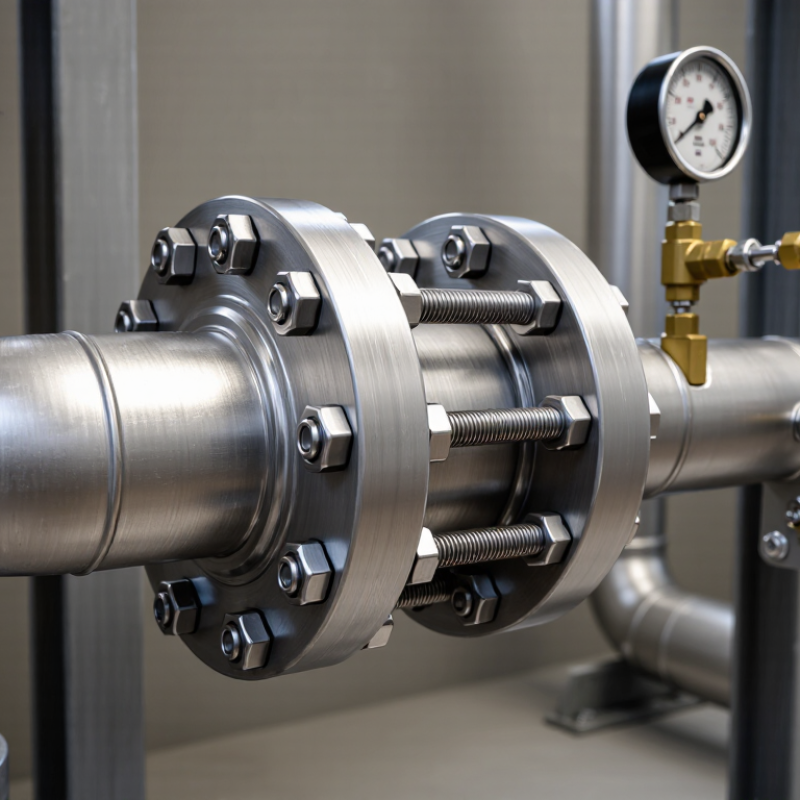
High-pressure clamps are not interchangeable. Split clamps suit repeated inspection, while two-bolt pipe clamps work better on fixed hydraulic lines. Tube clamps are compact, but they need correct support spacing and compatible inserts. For flexible hose assemblies, a safety clamp can limit whip after coupling failure. It cannot repair a damaged hose.
Start with pressure, temperature, fluid, and outside diameter. Check both working pressure and transient pressure, because pumps can create short pressure spikes. ISO 4413 requires hydraulic systems to control stored energy and prevent hose movement. ASME B31.3 also emphasizes pressure design, material suitability, and inspection for process piping. These standards guide selection, but they do not replace the manufacturer’s tested service limits.
Market data shows why this decision matters. The 2024 MarketsandMarkets Hydraulic Equipment Market report projects growth from USD 46.6 billion in 2023 to USD 55.7 billion by 2028. More equipment means more connections under demanding conditions. Still, market growth does not prove a clamp is suitable. Engineers should compare rated pressure, temperature range, corrosion resistance, bolt torque, and vibration performance. A clamp rated for 10,000 psi may fail earlier when misaligned or overtightened. I have seen drawings list pressure but omit temperature. That gap deserves review. Use a documented installation record, recheck torque after commissioning, and replace components showing cracks, deformation, or chemical swelling.
Choosing a high-pressure clamp starts with the flange, not the clamp label. Confirm nominal size, outside diameter, bolt-hole pattern, facing type, and gasket dimensions against ASME B16.5. The standard covers flanges and flanged fittings, but it does not automatically certify every clamp assembly. That distinction is easy to miss.
Pressure class must match the real pressure-temperature condition. For one carbon-steel material group at 100°F, ASME B16.5 lists approximately 285 psi for Class 150, 740 psi for Class 300, 1,480 psi for Class 600, 2,220 psi for Class 900, 3,705 psi for Class 1500, and 6,170 psi for Class 2500. These values change with material and temperature. A clamp rated at room temperature may lose capacity sharply near a hot process line. Check the pressure-temperature tables, not only the class number. (ASME B16.5-2022, Table 2)
Field experience also favors checking assembly behavior. Measure flange misalignment, surface damage, bolt engagement, and gasket compression before installation. A clamp can fit a six-inch flange yet fail to provide uniform sealing if the faces are uneven. ASME PCC-1 recommends controlled bolting practices because uneven preload can create leakage paths. I would also request test records, material certificates, and proof-pressure results. In practice, this step is sometimes skipped. That is a weakness worth challenging, especially on Class 1500 or Class 2500 service.
Selecting a high pressure clamp for sour service requires more than checking pressure and size. ISO 15156/NACE MR0175 should guide material selection when hydrogen sulfide may be present. H2S can trigger sulfide stress cracking, even when the clamp appears mechanically strong. Start with the operating envelope. Record pressure, temperature, H2S partial pressure, chloride level, pH, and exposure duration. These details influence material limits and testing requirements.
Tips: Confirm the clamp body, bolts, nuts, and washers meet the same sour-service expectations. Check hardness limits, heat treatment records, and mill certificates. Ask for material traceability. Do not accept a generic stainless steel description as proof of compliance. Alloy performance depends on processing and environment. A qualified engineer should review the final selection against the current ISO 15156/NACE MR0175 requirements.
In practical inspections, pay attention to threads, sharp edges, and damaged coatings. Stress concentration often begins in small, overlooked areas. Use compatible sealing materials, and verify that installation torque matches the design procedure. Field repairs can change hardness or introduce contamination. That risk is easy to underestimate. Clamp qualification should include documented testing, inspection records, and clear service limits. No checklist is perfect. Actual conditions may differ from the original design basis, so reassess the clamp after process changes, temperature excursions, or unexpected corrosion evidence.
Choosing a high pressure clamp starts with the port, not the clamp body. In field inspections, I have seen mismatched flange heads leak even when their pressure ratings looked identical. SAE J518 interfaces commonly use four-bolt split flanges, with Code 61 for 3,000-PSI service and Code 62 for 6,000-PSI service. Confirm the code from the equipment drawing or identification plate. Do not trust appearance alone.
Measure the flange size, bolt-hole spacing, pilot diameter, port opening, and O-ring groove. Check the groove depth and sealing face for damage. A small geometry error can tilt the clamp halves and create uneven compression. Verify the bolt pattern before ordering. Also confirm whether the system rating applies to the complete assembly, not only the flange. Actual limits may change with size, temperature, material, and pulsation.
Fit matters most.
During selection, compare the clamp halves with the exact SAE J518 interface. The 3,000-PSI and 6,000-PSI versions may look similar, yet their dimensions and service limits can differ. Use calibrated calipers and a current engineering drawing when possible. Clean the sealing surfaces before inspection. Never compensate for a wrong fit by overtightening bolts. That can distort the flange or damage the O-ring.
My early mistake was measuring only the outer flange width. It missed the bolt spacing. A better check uses three points: geometry, seal condition, and verified pressure duty. Recheck all three before installation.
Compare the selected clamp and port geometry with the SAE J518 interface class before installation. Code 61 is commonly identified with a 3,000 psi nominal class, while Code 62 is commonly identified with a 6,000 psi nominal class. Actual allowable working pressure depends on flange size, material, temperature, mounting hardware, hose assembly, and the applicable manufacturer or system specification.
Choosing the right high pressure clamp starts with more than matching pipe diameter. Check the clamp’s rated pressure at the actual operating temperature. Heat can reduce material strength and seal performance. Confirm compatibility with the fluid, pipe material, vibration level, and expected movement. A useful safety factor should reflect the system’s pressure spikes, not only its normal reading. Undersized bolts or uneven loading can create hidden stress.
Pressure testing must happen before installation is accepted. Use a documented procedure and calibrated gauges. Follow the applicable engineering standard and site safety controls. Hydrostatic testing is often preferred because it stores less energy than pneumatic testing, but the selected method depends on the system and risk assessment. Inspect for leakage, distortion, slipping, and pressure loss. Do not stand near potential release points. A clamp may look secure while the pipe shifts slightly under load.
Tips: Ask for material certificates, batch or heat numbers, inspection records, and test results. Match each record to the actual clamp. Verify bolt grade, seal batch, and torque requirements. Keep photographs and installation readings in the project file. I have seen traceability treated as paperwork, then needed during a failure review. That is a costly lesson. Records should be clear enough for another engineer to check without guessing. If any certificate is incomplete, pause installation and investigate it. A perfect checklist cannot replace sound judgment.
Check flange size, outside diameter, bolt-hole pattern, facing type, and gasket dimensions. The clamp label is not enough.
No. The flange standard does not automatically certify every clamp assembly. Review separate qualification and test records.
Pressure capacity can fall as temperature rises. At 100°F, Class 150 may allow about 285 psi for one carbon-steel group.
No. Match the actual pressure-temperature condition with the correct material table. A room-temperature rating may mislead.
Misaligned faces, surface damage, poor bolt engagement, and uneven gasket compression can create leakage paths. Small defects matter.
Use controlled bolting and follow the design torque procedure. Uneven preload may leave one side visibly tighter.
Record pressure, temperature, hydrogen sulfide partial pressure, chloride level, pH, and exposure duration. Conditions can change.
Verify the body, bolts, nuts, and washers. Check hardness, heat treatment, mill certificates, and traceability.
Inspect threads, sharp edges, damaged coatings, and field repairs. These areas can concentrate stress or introduce contamination.
Reassess after process changes, temperature excursions, or unexpected corrosion. No checklist catches everything. That is the uncomfortable part.
Choosing the right High Pressure Clamp requires more than matching a nominal pipe size. Begin by identifying the clamp type and its intended application, then confirm that its size, pressure rating, and operating temperature align with the system requirements and the relevant ASME B16.5 Class 150–2500 range. Consider pressure cycles, vibration, installation space, and maintenance access to ensure the selected design is practical and reliable.
Material selection is especially important in corrosive or sour-service environments. Evaluate compatibility according to ISO 15156/NACE MR0175 criteria, including resistance to cracking and degradation. The clamp’s port geometry must also match the required SAE J518 3,000- or 6,000-PSI interface to prevent leakage and assembly problems. Before installation, review safety factors, confirm pressure-test results, and verify complete material and manufacturing traceability. Careful documentation and inspection help ensure the clamp performs safely throughout its intended service life.

Minde